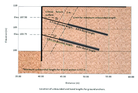
Autodesk Robot Structural and the Ground Anchors.
In fact, Autodesk RSA is not a specif application for the designing of ground anchors.
But their tools for evaluating ground loads can be extremely useful in the work of designing a ground anchors containment system.

Knowing this thrust necessary before you can make the decision on which is the most appropriate containment system and make the decision between shoot crate walls, steel mesh reinforcement, solider beam and lagging or a big reinforcement concrete containment wall.
In this document, we will make a comparison between the land loads thrown by Autodesk Robot Structural analysis and those obtained by the diagram of apparent pressure of the land used by the Federal Administration of roads of the Department of transportation of United States (FHWA), which are employed by the AASHTO.
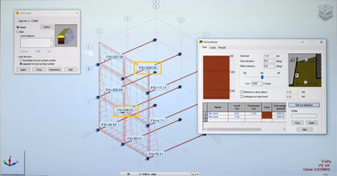
Let's observe that FHWA-AASHTO uste the method of apparent envelope of the ground pressures of Terzaghi and Peck, in terms that Autodesk RSA uses a method of increasing the thrust of the soil in proportion to the depth of the excavation, the geothecnical profile, K coefficient, groundwater level and the nearest structures weights.
This allow us to take Autodesk Robot Structural as a reliable tool for quickly getting the load value of the land within a range of acceptable values.
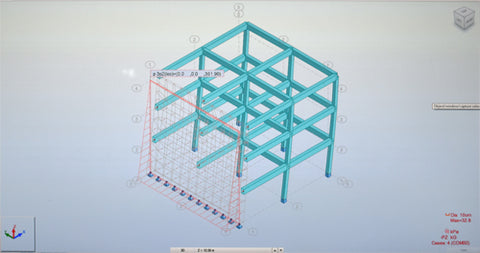
To emulate this containment screen supported by ground anchors, we have sketched in Autodesk RSA an element of reinforced concrete composed by walls based on two-directions slabs.
From these interceptions depart tensors into a virtual land, that is ten meters deep, sustained by elastic supports with a certain coefficient of ballast, calculated by the geothecnical Robot's calculator.
The conditions for the volumetric weight, friction angle and overload of the traffic are the same from the example. However, note that the geometry of the envelope in Autodesk RSA load differs from the one considered by the Terzaghi and Peck for the diagram of apparent pressure from the soil.
We cannot say that is wrong, but it should be noted that both methods applied to the tributary area, as is is in the joint area, part from steel elements driven deep into the suitable land that is help by anchors to specified levels.
 Robot
Structural specifically calculates the load of the soil at rest,
pressing on a screen. We conclude that the values are not significantly
different and can be taken as a first exploratory data or approach, for
which we could quickly establish criteria for possible alternative
solutions.
But their tools for evaluating ground loads can be extremely useful in the work of designing a ground anchors containment system.

Knowing this thrust necessary before you can make the decision on which is the most appropriate containment system and make the decision between shoot crate walls, steel mesh reinforcement, solider beam and lagging or a big reinforcement concrete containment wall.
In this document, we will make a comparison between the land loads thrown by Autodesk Robot Structural analysis and those obtained by the diagram of apparent pressure of the land used by the Federal Administration of roads of the Department of transportation of United States (FHWA), which are employed by the AASHTO.
Let's observe that FHWA-AASHTO uste the method of apparent envelope of the ground pressures of Terzaghi and Peck, in terms that Autodesk RSA uses a method of increasing the thrust of the soil in proportion to the depth of the excavation, the geothecnical profile, K coefficient, groundwater level and the nearest structures weights.
None is wrong about the other. They are two
approaches to the same problem. And both solutions coincide in the
middle of the graph and the general maintain approximate values for the
same ground conditions. In any way exists a coefficient of the
uncertainty in relation to the soil loads called K.
This allow us to take Autodesk Robot Structural as a reliable tool for quickly getting the load value of the land within a range of acceptable values.
To emulate this containment screen supported by ground anchors, we have sketched in Autodesk RSA an element of reinforced concrete composed by walls based on two-directions slabs.
From these interceptions depart tensors into a virtual land, that is ten meters deep, sustained by elastic supports with a certain coefficient of ballast, calculated by the geothecnical Robot's calculator.
The conditions for the volumetric weight, friction angle and overload of the traffic are the same from the example. However, note that the geometry of the envelope in Autodesk RSA load differs from the one considered by the Terzaghi and Peck for the diagram of apparent pressure from the soil.
We cannot say that is wrong, but it should be noted that both methods applied to the tributary area, as is is in the joint area, part from steel elements driven deep into the suitable land that is help by anchors to specified levels.
 Robot
Structural specifically calculates the load of the soil at rest,
pressing on a screen. We conclude that the values are not significantly
different and can be taken as a first exploratory data or approach, for
which we could quickly establish criteria for possible alternative
solutions.
For more information visit www.virginiae-learning.com

No comments:
Post a Comment