Tuesday, June 5, 2018

Which Structural Analysis software is the most precise?

Perhaps for many of you already familiar with Structural Analysis software, this question makes no much sense whatsoever.
 
Nonetheless, and believe it or not, this a very common question among those fellow engineers how are not sure about moving into a computer aided solution for Analysis, Design and Calculation of Structures.
Of course, this question has an honest real concern behind it, since if you base your design in the analysis results of a faulty program, you could seriously be  putting lives at risk, or your career at the very least...
So, and for those who are really looking for an answer to this question, the answer is...all of them...

Or to be "precise", the one software being imprecise will be the big exception among all them.

You will have to be looking for a Structural Analysis software in the "wrong places" to find such a marvel of programming.

But let me clarify things for you, just in case this last argument isn't convincing enough.

Asking which Structural Analysis software is "the most precise"  is just like asking which calculator among any of your computers (if you own more than one) is the most precise...

Well obviously, and to begin with, any of them will be far more accurate when solving complex integrals in infinitesimal calculations than any human being. And far more reliable...

Furthermore, calculations for the Analysis of a Structure performed manually are based in approximation methods (plastic and elastic analysis methods). And it couldn't be otherwise...that's why we use computers in the first place...

  
Are you getting the picture yet?

So, how accurate a Structural Analysis software can be? Simple...as much as computer can...
But if that's so, then why do we find structures calculated through a computer which look actually less robust than those calculated in a more "traditional" way?

The answer is also simple...criteria and experience.

Most seasoned Structural Engineers have already a set of criteria based upon experience. One may even say they can "feel" what's right. But more often, they already know what works.

Of course this doesn't mean that when put into practice, the resultant design of the Structure is 100% efficient, in fact this may be "over-calculated". But it gets the job done and it does it well.

So when we pair of up the results from an Structural Analysis, one made by your favorite analysis software and another by traditional means, there's always discrepancies.

But not because of the program messing up, but because this tends to be way more accurate than any calculation done manually.

Specially, when NO CRITERIA from the structural engineer is applied on the side of the computer.

Or even worst, when there's no clear idea on how to apply the correct Design Code inside the software being use...that would be indeed a fatal flaw of which the program isn't guilty at all.

Of course, none of us should ever picture a structural design which doesn't comply with the required Design Code.

But the sad reality, is that some rookies have no clue of what that Design Code of the particular country or region in which the project is being built says or does exactly. And they expect the program to "Auto-magically" know what to do when analyzing the design.

And in the bottom of my heart, I know this is the real reason behind questioning the level of accuracy of the results produced by a given program...

What if the results of the program aren't accurate!!??

....Shouldn't you be able to tell just by performing the analysis of a simple Steel Frame?

Well, if you have no clue of how the Design Code should rule a particular Design, or if you aren't "in tune" with how the Analysis of a Structure is performed...you may be in trouble.

So my honest advice is not to worry so much about the level of accuracy provided by a particular Structural Analysis software, is always going to be far higher than of any human being, and begin worrying more about becoming more proficient in Structural Analysis in general...and yes sit down and read the Design Code that concerns you. And understand how this affects the overall design of your structure.

But just in case you aren't fully convinced, Autodek RSA displays inside its many calculation reports, all the correspondent formulas being used, and how each of the results are being applied throughout the analysis.

So you may even perform a manual verification if you must.

For more information about Autodesk Robot Structural Analysis Professional, visit www.virginiae-learning.com


Wednesday, September 20, 2017

Emulation for optimal structural design.

Emulation for optimal structural design.


If you are fond to ancient world engineering and the surprising achievements of the humanity such as the  Pyramid of Egypt, you will notice that the Pharaohs of the ancient empire  had to perform some failed attempts before they could build the Giza Pyramids Complex. After the famous engineer, architect and erudite Imhotep built the  stepped Saqqara pyramid, of seventy meters high, the precedent Pharaohs attempted the construction of next level pyramids.

But the next attempt, the Medium pyramid, ended up collapsing under its own weight, while the next one, the Dahshir pyramid, had to suddenly change its angle, since the collapse of its internal structure seemed to be unavoidable.

We had to wait until the Red Pyramid at short distance from the previous one, for achieving the adequate resting angle for obtaining the proper structural integrity.
Red Pyramid
Thousands of years later, during the XIX century when the railroad network extended to all the corners of the industrialized countries Great Britain and  United States, as the leaders, the need of saving chasms and rivers, fomented the construction of bridges.

Not everybody was successful, Stirling, Broughton, Chester, Wooton, Tay in Scotland and Inerythan, were example of this delirious and tragic beginning of the structural engineering in the United Kingdom of the industrial revolution.

North America, also had its named failures, some already during the 20th century and several filmed as classic catastrophes movies.

All these structural failures that costed dozens of deaths and wounded helped as experience so we can now enjoy of safer structures, but  not quite still.

Even so this doesn't mean we  no longer have structural failure. New needs present new challenges. The frail for urban space leads to the constriction of structures simultaneously higher and deeper, where the deep excavations incidents present themselves at an alarming rate.

Here is where structural analysis software such as Autodesk Robot Structural permits us design structures and test them before wind or seismic load cases that may be catastrophic. Including big frames structures subjected to accidental loads.
Accidental Loads
This doesn't mean though that we should design thinking always on the catastrophes. Actually there's regulations and design codes regarding the cases that should be considered. The safety coefficients that should be respected and the accidental load cases that must be included.

In more practical cases, Autodesk RSA permits us to try different structural proposals without more work than changing  the beams and columns section selection.

It's not unusual, that our first structural proposal happens to be somehow oversized. We all design with certain degree of fear that our design calculations present some error or that our sections cant bear the loads. Furthermore, that the design loads won't be respected and that the structure get overloaded. It's something rather common.

Autodesk Robot Structural allows us to observe the deformations in the structure in a graphic way before all the different load cases and combinations. The structure deforms affected by the a certain scale, so we can further appreciate each load effect.

From there we could verify the shear and bending moment graphs, but the most evident aspect is observing the deformations as we check each section.
Structural Deformations
With this information we can test different sections until we get to a solution that offer us the best relation between safety and economy.

It's easy to switch structural elements of steel or reinforced concrete and observe the deformations and critical points.

Before the same set of load cases combinations we can check different steel and concrete elements, observing the results through deformation that may be animated, but that will throw the results in a way of a color code and precise values over the deformation points.
Since we can determine the deformation scale, is quite easy to appreciate how the stresses are exerted over the structure.

From these first results and the real-time displayed safety coefficients it's possible to switch structural elements for slimmer or lighter members and observe the deformation and coefficient changes.

The simulation can be taken to a critical point and from there test members, connections or far more creative geometry elements that resolve the transfer of weight and stresses in a more clever way,so we can obtain lighter and more resistant structures.

As oppose to other calculation programs where the changes in the structure involves a long process of mathematical rethinking, in Autodesk Robot Structural such process is graphical making the analyst feel motivated to perform a bigger amount of changes y tests, as if it was some sort of virtual construction game.

The effects of each change in the structure are also displayed in a graphical way, being possible to work with complete combinations involving wind, seismic and accidental loads, including any other event to which the structure could be subjected along with its respective foundation.

published by Virginia E-Learning.

Thursday, September 14, 2017

Autodesk Robot Structural and the Ground Anchors.

Autodesk Robot Structural and the Ground Anchors.


In fact, Autodesk RSA is not a specif application for the designing of ground anchors.
But their tools for evaluating ground loads can be extremely useful in the work of designing a ground anchors containment system.
Retaining Walls
Knowing this thrust necessary before you can make the decision on which is the most appropriate containment system and make the decision between shoot crate walls, steel mesh reinforcement, solider beam and lagging or a big reinforcement concrete containment wall.

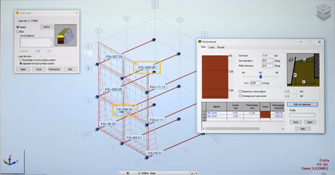
In this document, we will make a comparison between the land loads thrown by Autodesk Robot Structural analysis and those obtained by the diagram of apparent pressure of the land used by the Federal Administration of roads of the Department of transportation of United States (FHWA), which are employed by the AASHTO.

Let's observe that FHWA-AASHTO uste the method of apparent envelope of the ground pressures of Terzaghi and Peck, in terms that Autodesk RSA uses a method of increasing the thrust of the soil in proportion to the depth of the excavation, the geothecnical profile, K coefficient, groundwater level and the nearest structures weights.
Robot Structural 2018 Walls
None is wrong about the other. They are two approaches to the same problem. And both solutions coincide in the middle of the graph and the general maintain approximate values for the same ground conditions. In any way exists a coefficient of the uncertainty in relation to the soil loads called K.

This allow us to take Autodesk Robot Structural as a reliable tool for quickly getting the load value of the land within a range of acceptable values.
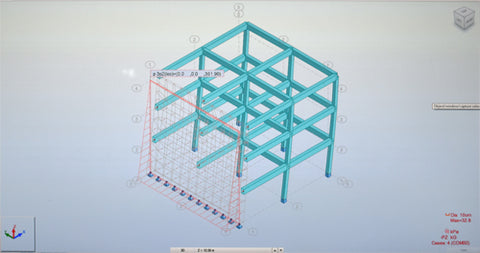
To emulate this containment screen supported by ground anchors, we have sketched in Autodesk RSA an element of reinforced concrete composed by walls based on two-directions slabs.

From these interceptions depart tensors into a virtual land, that is ten meters deep, sustained by elastic supports with a certain coefficient of ballast, calculated by the geothecnical Robot's calculator.

The conditions for the volumetric weight, friction angle and overload of the traffic are the same from the example. However, note that the geometry of the envelope in Autodesk RSA  load differs from the one considered by the Terzaghi and Peck for the diagram of apparent pressure from the soil.

We cannot say that is wrong, but it should be noted that both methods applied to the tributary area, as is is in the joint area, part from steel elements driven deep into the suitable land that is help by anchors to specified levels.
Ground AnchorsRobot Structural specifically calculates the load of the soil at rest, pressing on a screen. We conclude that the values are not significantly different and can be taken as a first exploratory data or approach, for which we could quickly establish criteria for possible alternative solutions.

For more information visit www.virginiae-learning.com

Friday, August 11, 2017

Robot Structural 2018 Tutorial | Retaining Walls&Foundations in Deep Excavations

Robot 2018 Tutorial | Deep Excavations


This course focuses on the analysis and designing of Retaining Systems.

Allow Autodesk RSA to perform the retaining walls design, calculate the soil loads, consider the lateral soil pressure in high groundwater levels and the weight of nearby structures.
From Retaining Walls to Land Anchorages!

Furthermore, Autodesk RSA will also consider the elastic support of the soil; based on the given Geothecnical Study Profile.  It will also regard the soil pressure against the retaining wall, in a land anchorage system.
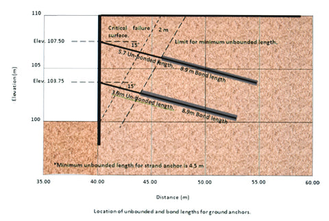
Robot Structural doesn't design by default land anchorages nor slopes. But it does provide the lateral push over the containment walls. Allowing us and from such data the designing of either the provisional or permanent retaining  systems.

Everything under the FHWA and ASSHTO code regulations!

Perform the seismic resistant analysis in underground structures and verify the reinforcing steel for the given seismic resistance!

  •      Foundations Analysis for Retaining Walls.
  •     Designing of Spread Footings.
  •     Designing of Continuous Footings.
  •     Designing of Retaining Walls.
  •     Designing of Retaining Walls of variable section.
  •     Designing of Retaining Walls with Speer.
  •     Designing of Slurry Walls.
  •     Designing of Foundation Slabs with elastic support.
  •     Seismic Resistant Design for Underground Structures.
  •     Designing of Retaining Walls of Volumetric Section.
  •     Loads Analysis on Land Anchorage Systems.
  •     Mechanically Stabilized Walls.
  •     Fails Analysis in Underground Structures.
  •     Groundwater influence analysis.
  •     Fails Simulation in Underground Structures.
  •     Includes Professional Online Support for all topics covered in this course!
To get this full tutorial visit: https://www.virginiae-learning.com

Sunday, July 24, 2016

Robot Structural Analysis 2017 │ Tutorial │ Sheet Piles │ Lesson 05

Robot Structural Analysis 2017 │ Tutorial │ Sheet Piles │ Lesson 05

Master the Analysis and Design of Foundations, Footings and Anchorages in Deep Excavations, with our Robot Structural Analysis Tutorial 2017, for Foundations and Deep Excavations. From Isolated and Continuous Footings, to Sheet Piles and Anchorages.
Don’t Forget to comment, like and subscribe to our channel.

For getting this tutorial visit: http://www.virginiaelearning.com/

Friday, July 22, 2016

Robot Structural Analysis 2017 │ Tutorial │ Anchorages & Retaining Walls │ Lesson 04

Robot Structural Analysis 2017 │ Tutorial │ Anchorages & Retaining Walls │ Lesson 04


Master the Analysis and Design of Foundations, Footings and Anchorages in Deep Excavations, with our Robot Structural Analysis Tutorial 2017, for Foundations and Deep Excavations. From Isolated and Continuous Footings, to Piles and Retaining Walls.

Don’t Forget to comment, like and subscribe to our channel!

For getting this full tutorial visit: http://www.virginiaelearning.com/

Thursday, July 21, 2016

Robot Structural Analysis 2017 Tutorial

Robot Structural Analysis 2017 Tutorial

For Foundations and Deep Excavations


For getting this tutorial visit: http://www.virginiaelearning.com/
Robot Structural Analysis 2017 │ Tutorial │ Foundations and Deep Excavations
For Foundations and Deep Excavations.


 Robot Structural Analysis 2017 Tutorial
Master the Analysis and Design of Foundations, Footings and Anchorages in Deep Excavations, with our Robot Structural Analysis Tutorial 2017, for Foundations and Deep Excavations. From Isolated and Continuous Footings, to Piles and Retaining Walls.

• Analysis of Reinforced Concrete Foundations.
• Isolated and continuous footing.
• Retaining walls.
• Underground Structures.
• Foundation Walls and Piles.
• Anchorages in deep excavations.